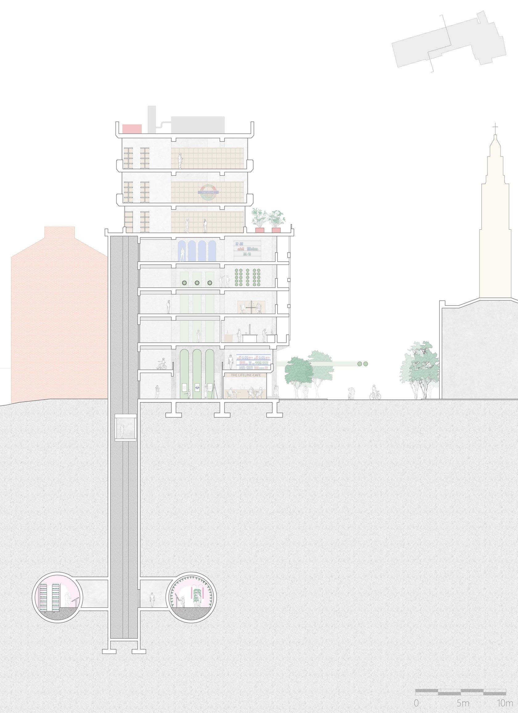
Cross Section of The Lifeline HQ
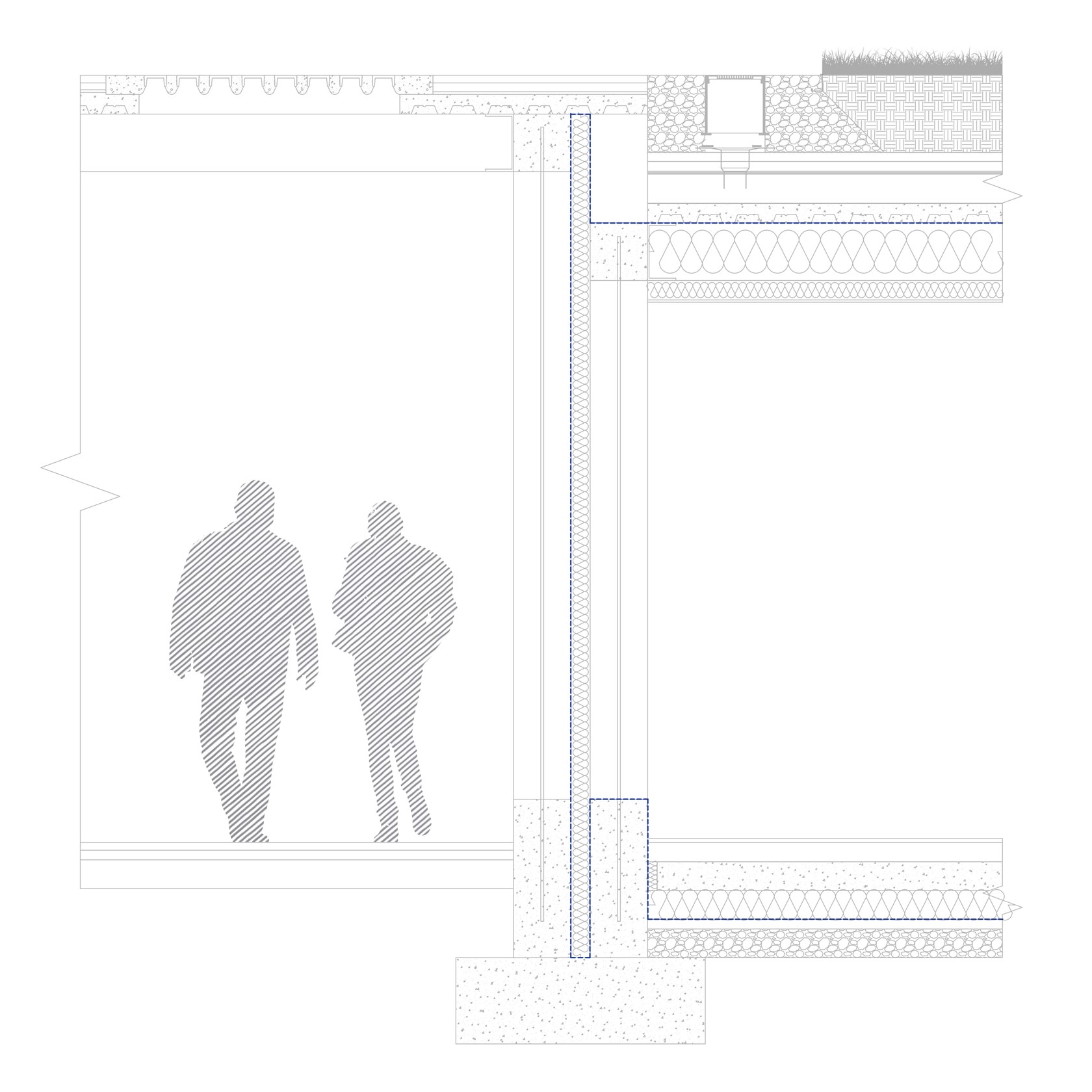
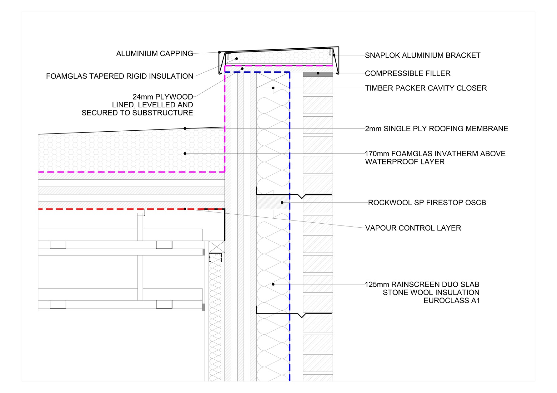
Technical close-up

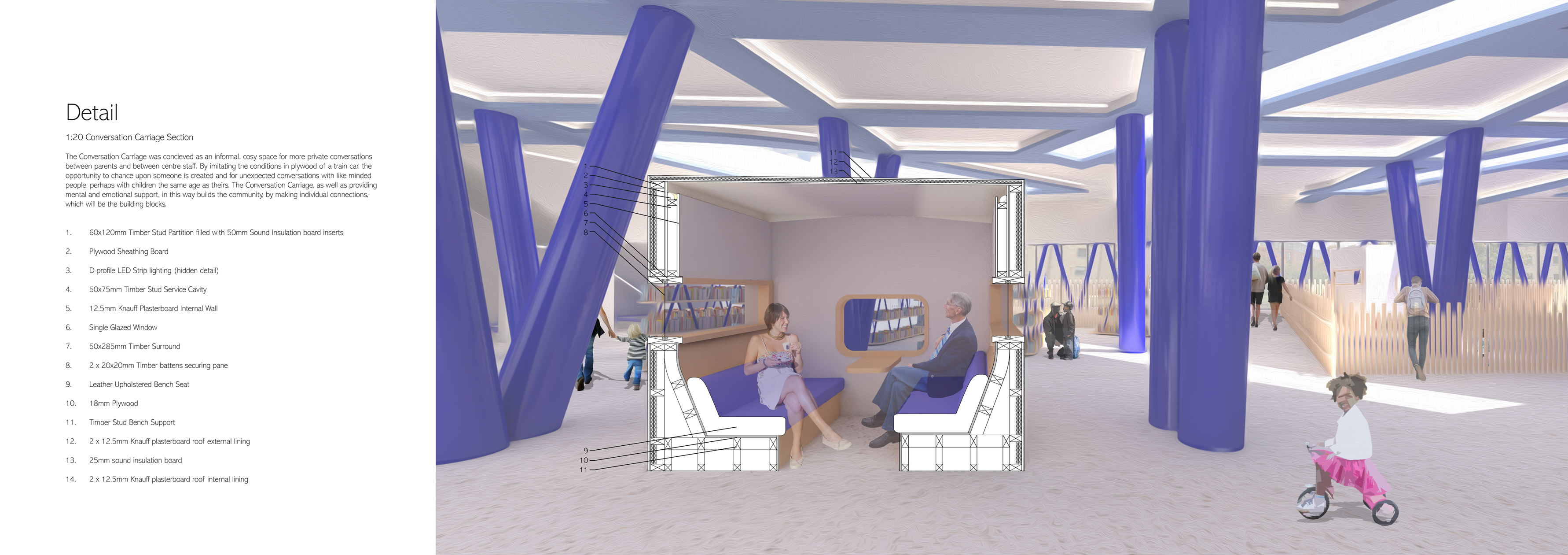
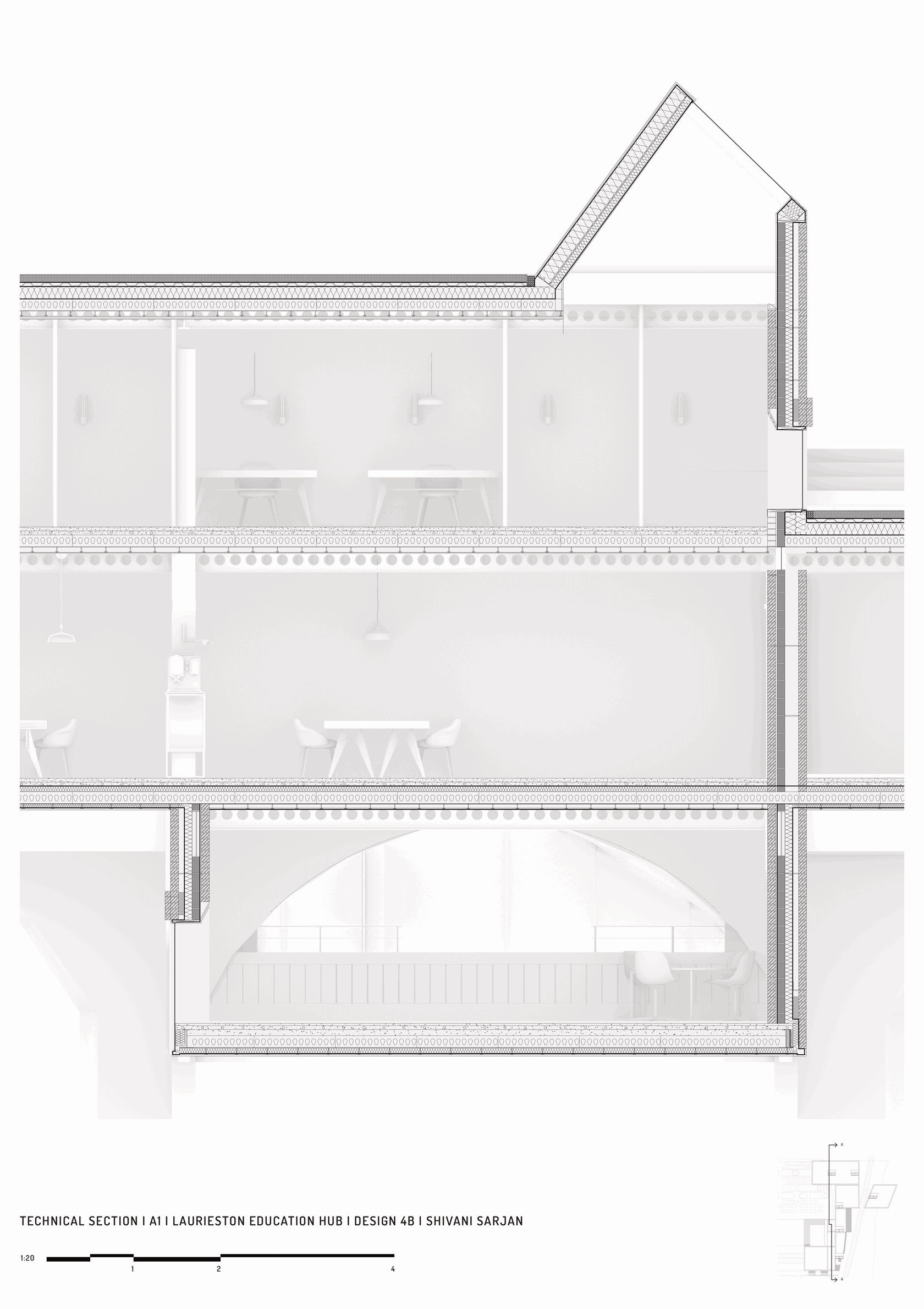
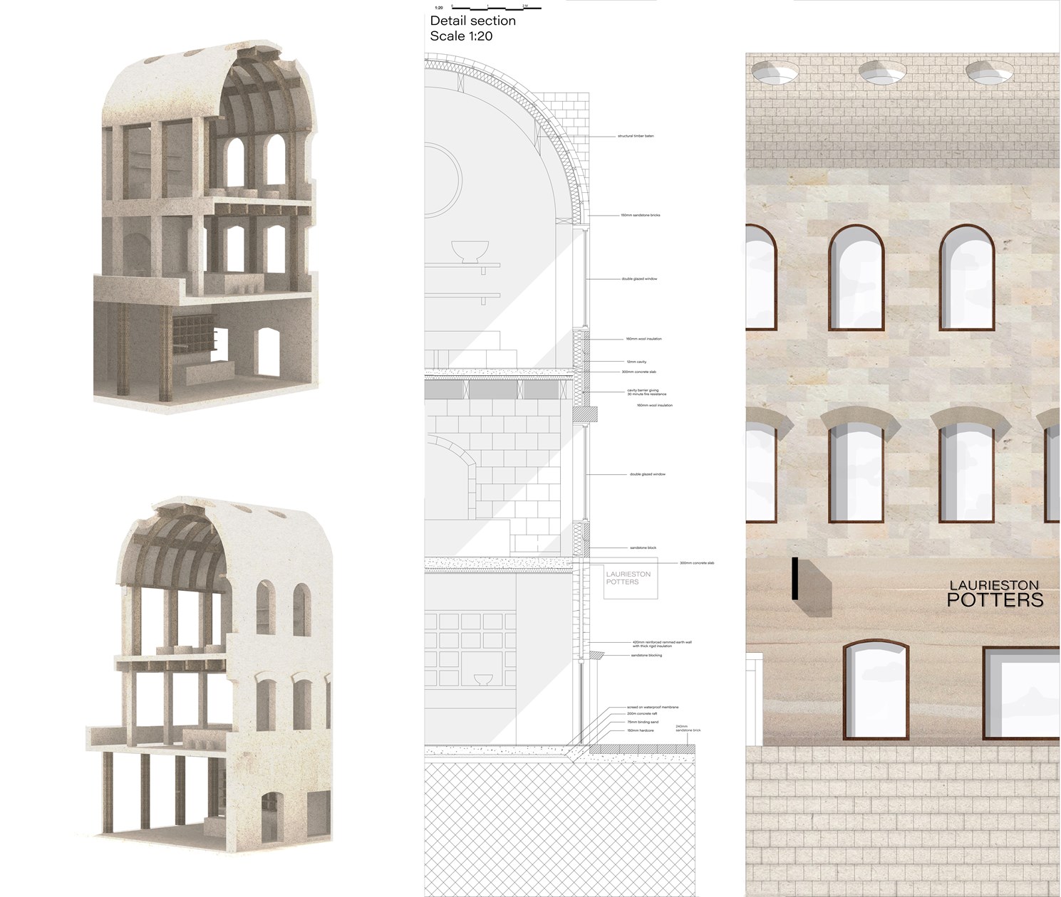
1:20 Interior Section Study
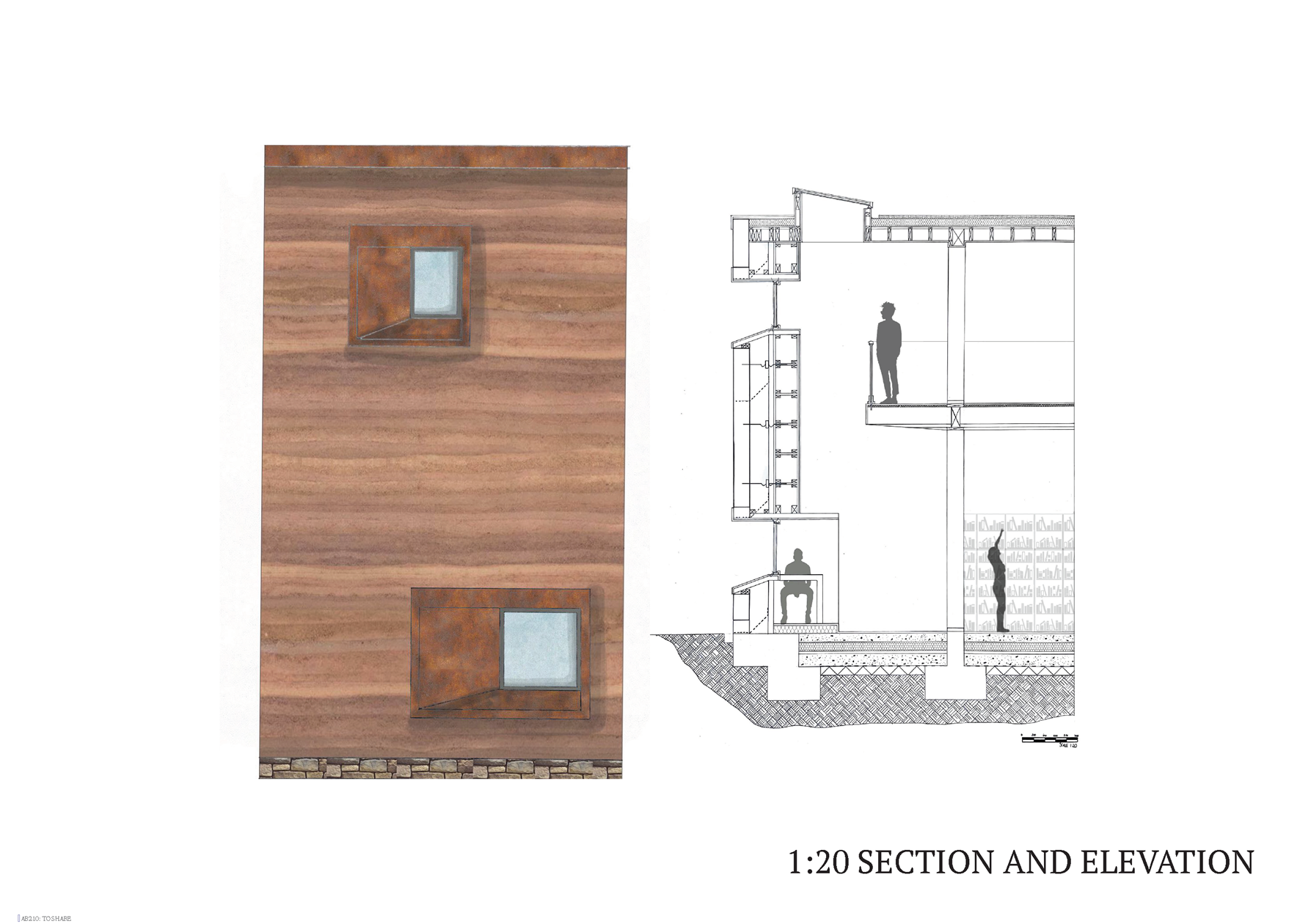
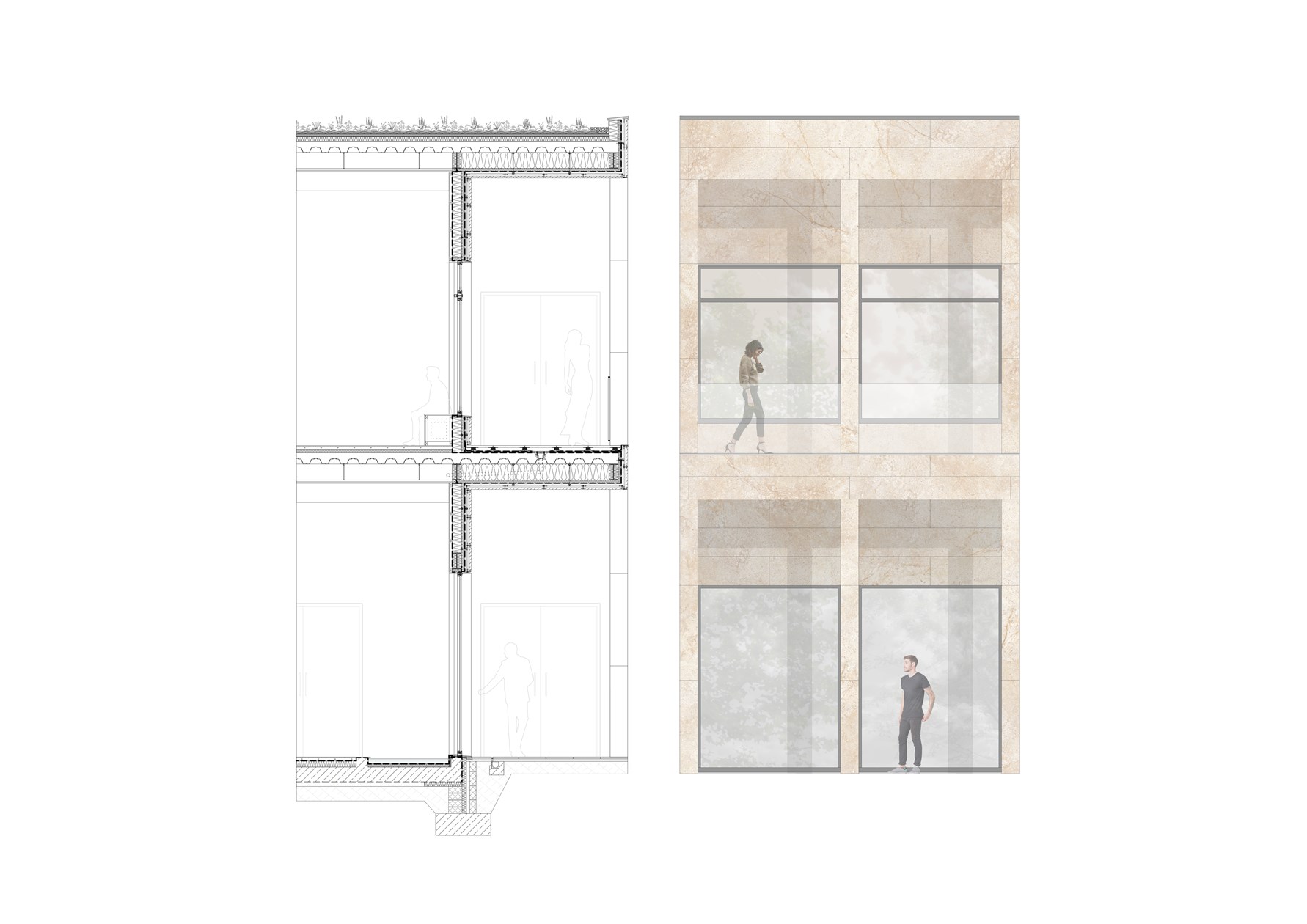
AB210: Technical Section and Elevation
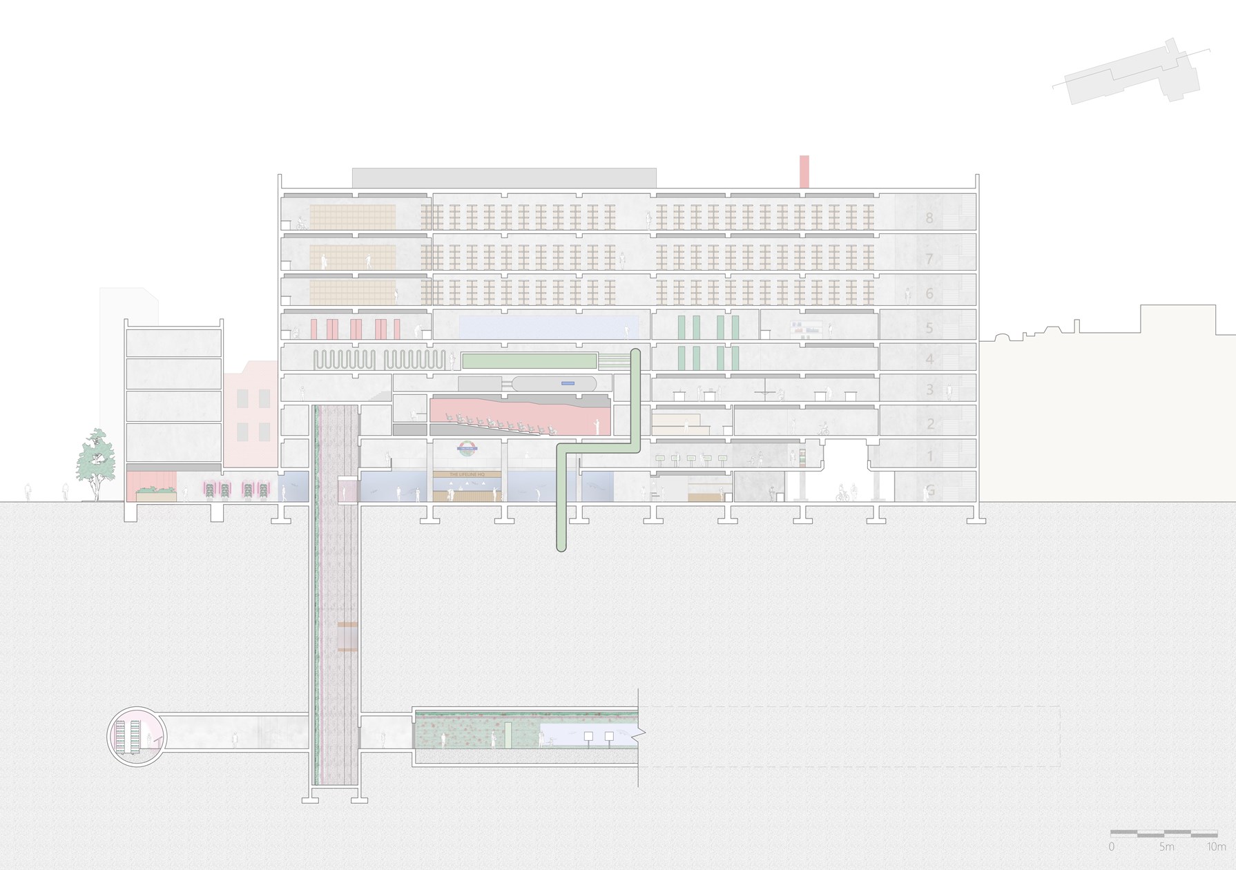
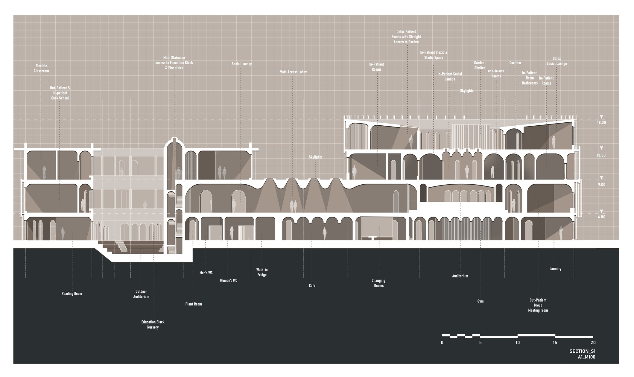
Longitudinal Section through The Lifeline HQ
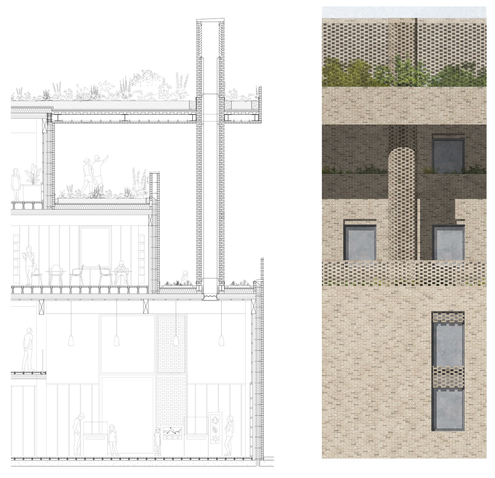
Technical Section and Elevation
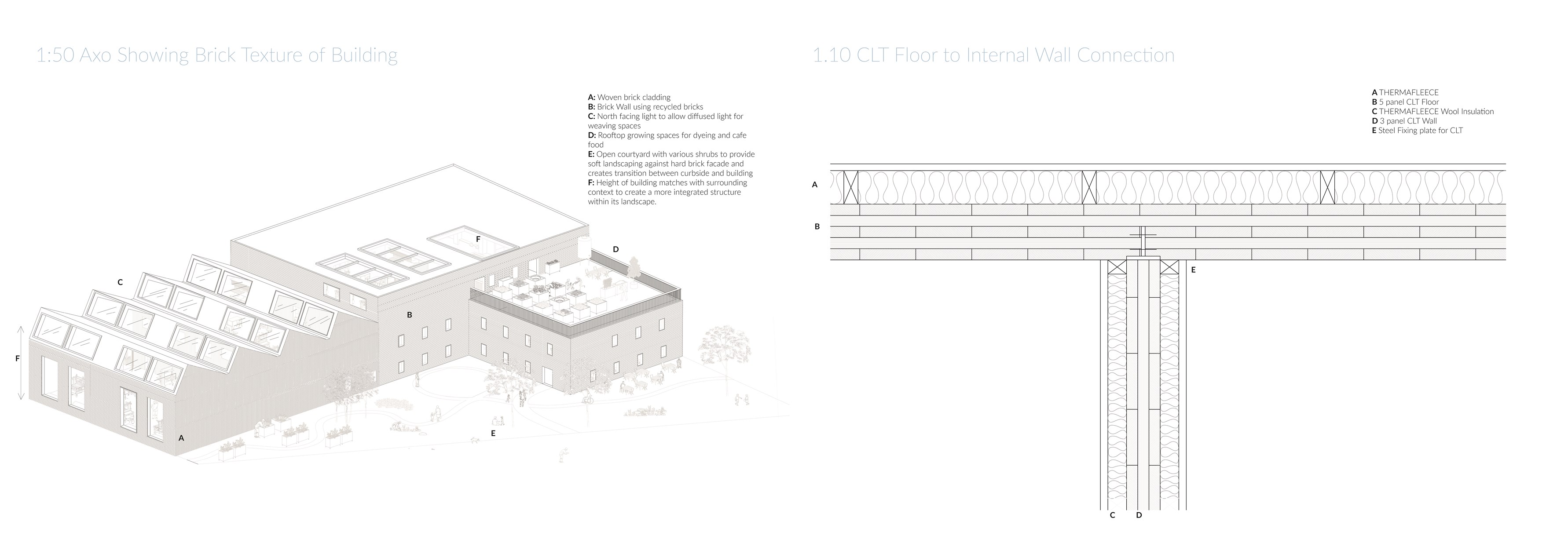
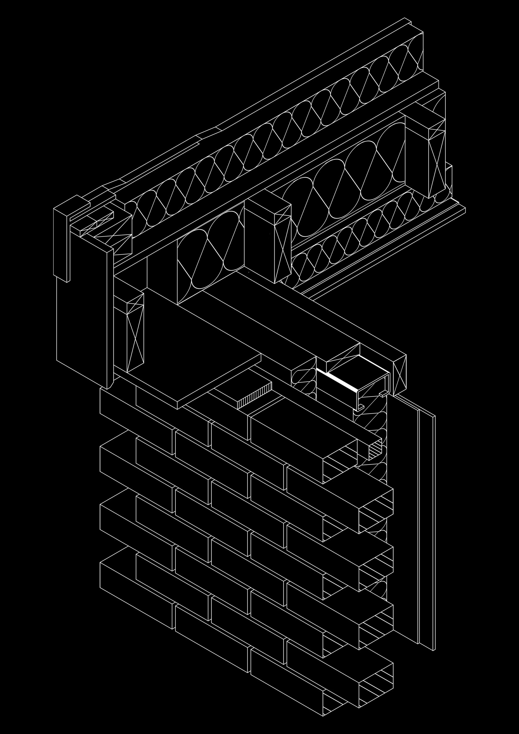
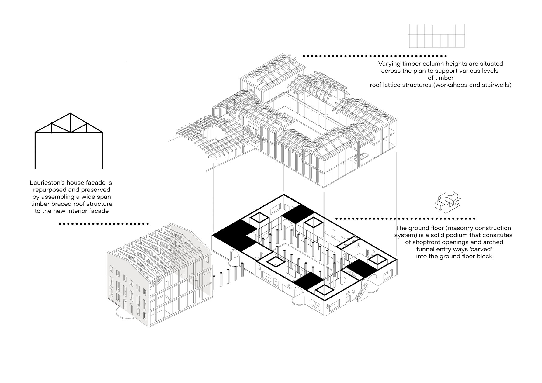
Axonometric with Floor to Internal Wall Detail
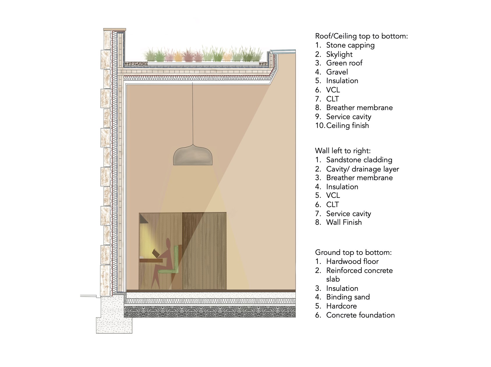
1:20 Section
Technical Drawing of Steel Frame - Timber Flat Roof
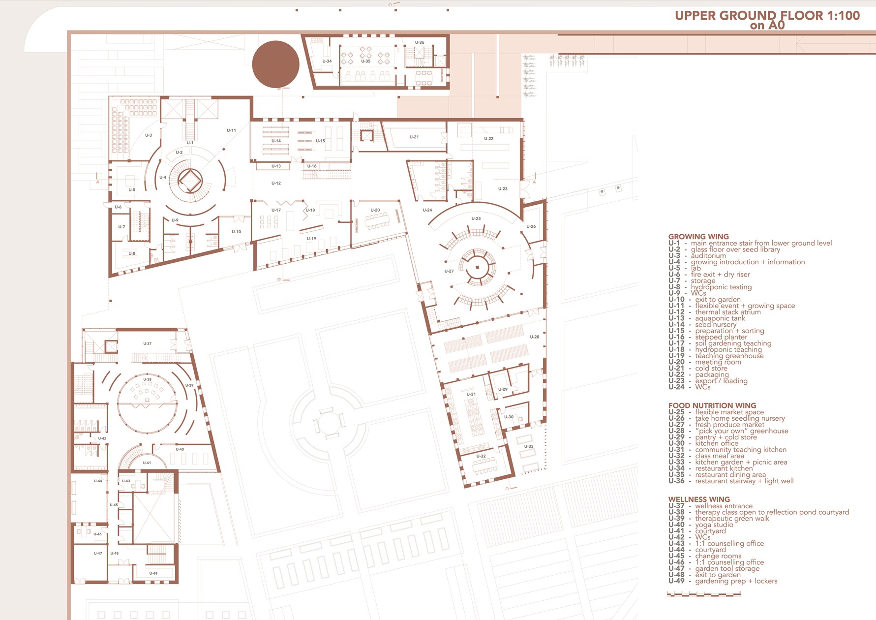
Upper Ground Floor Plan
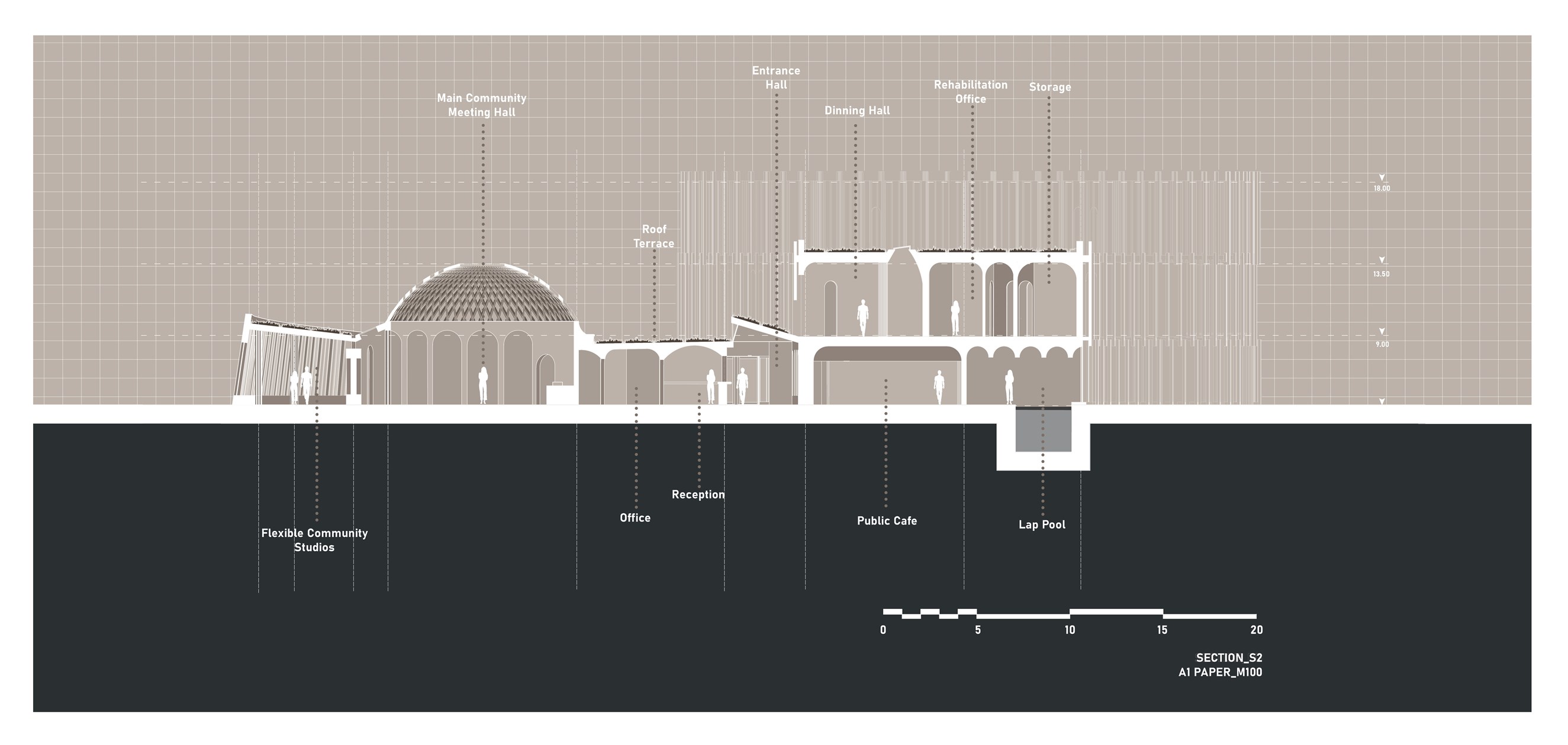
Building Section

1:100 South Short Section
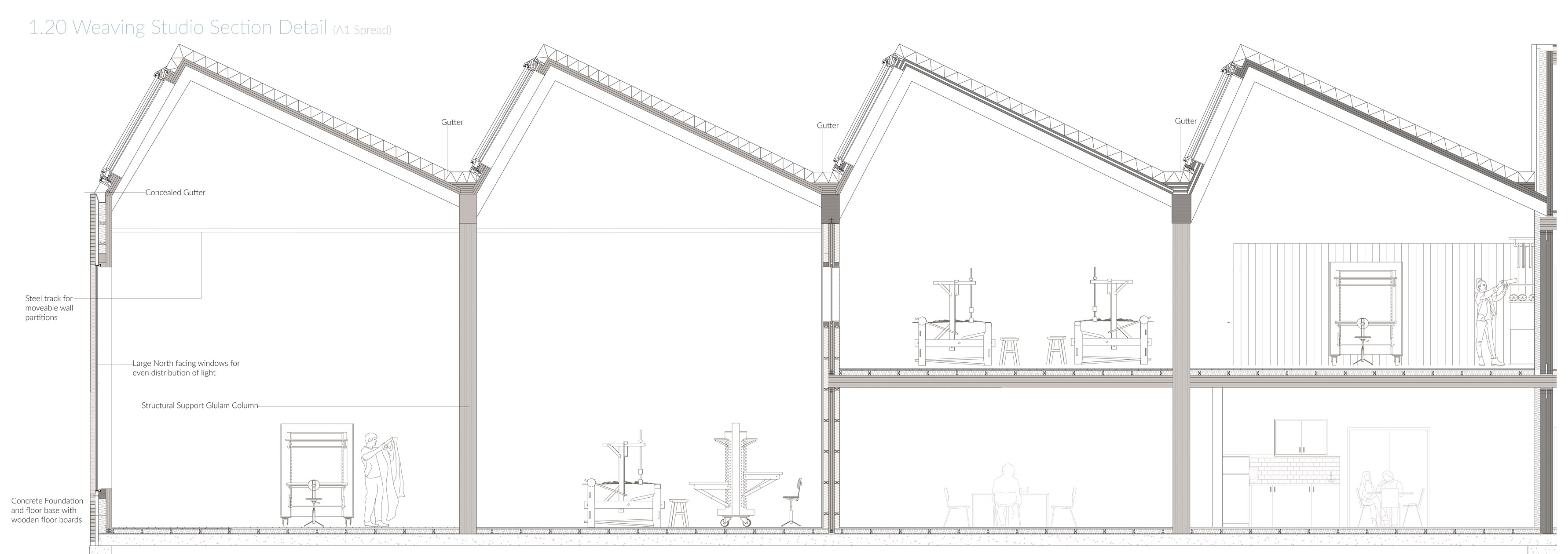
1:20 Technical Section of Weaving Studio
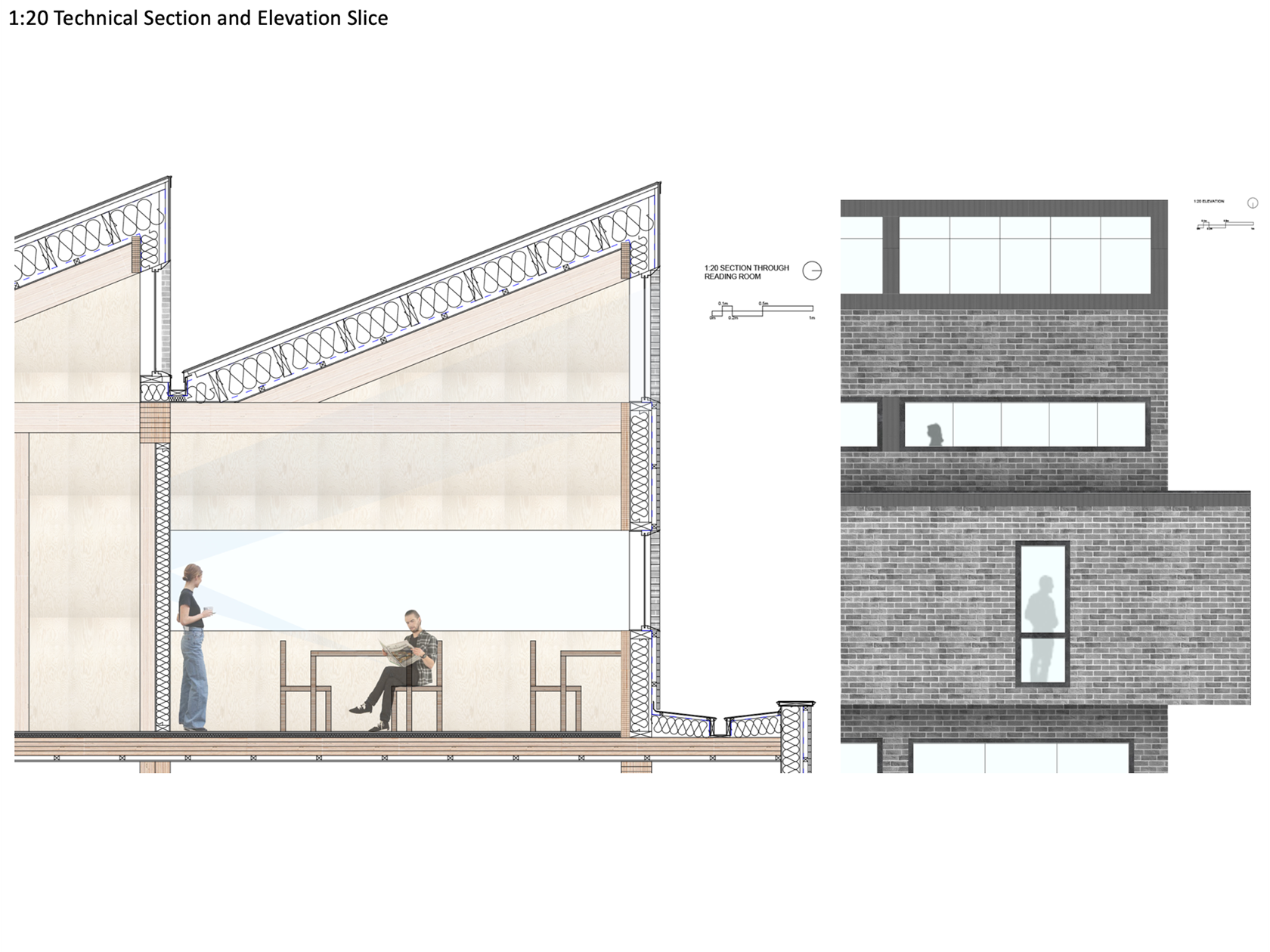
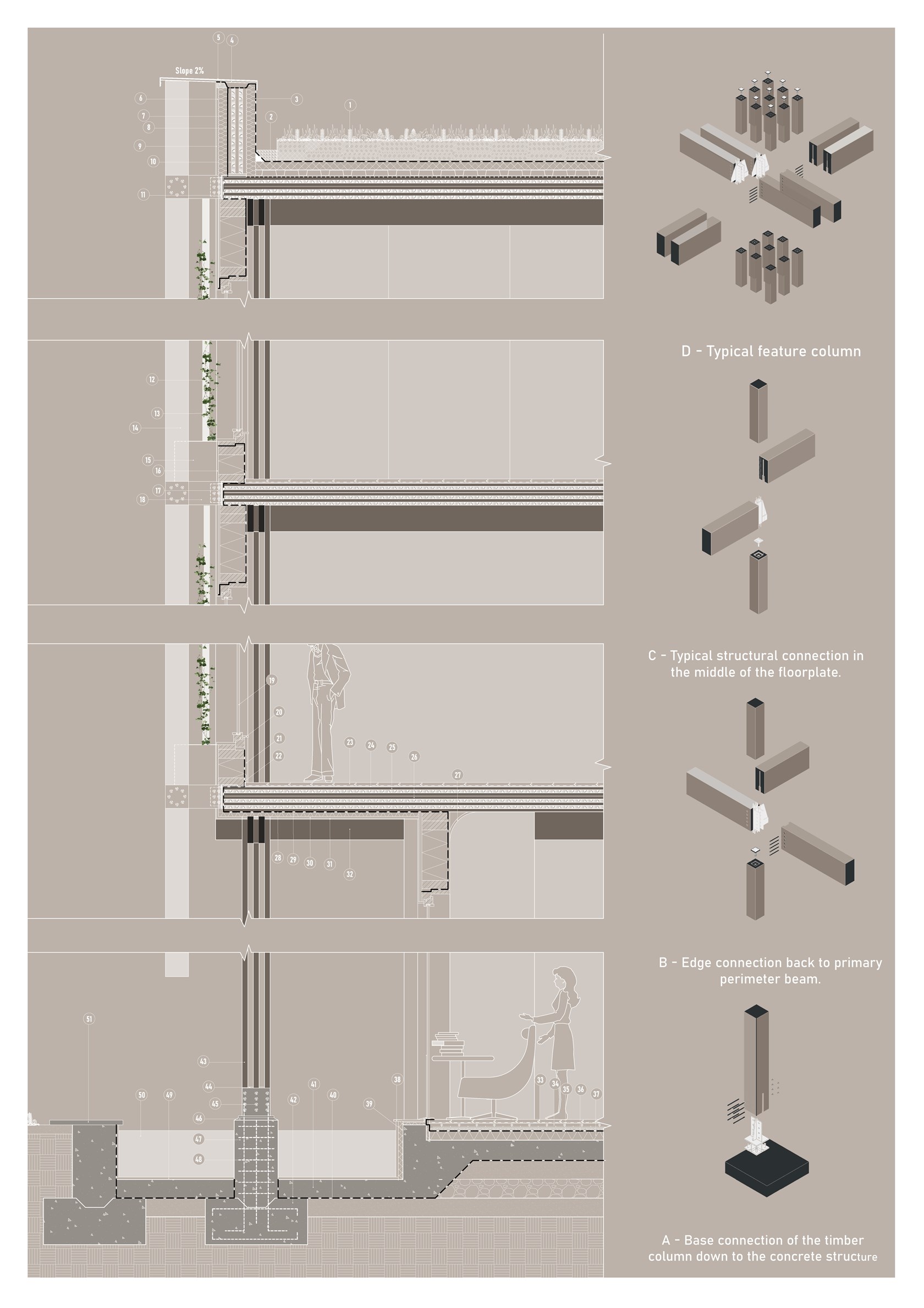
1:20 Technical Section and Elevation
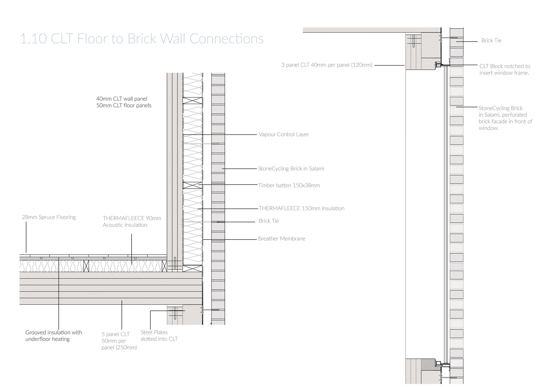
1:10 CLT Wall and Floor Connections
Technical Section

1:100 West Long Section

Plan section, junction of separating wall and external wall at 1:5
1:5 Technical Detail: Ground Floor to External Wall
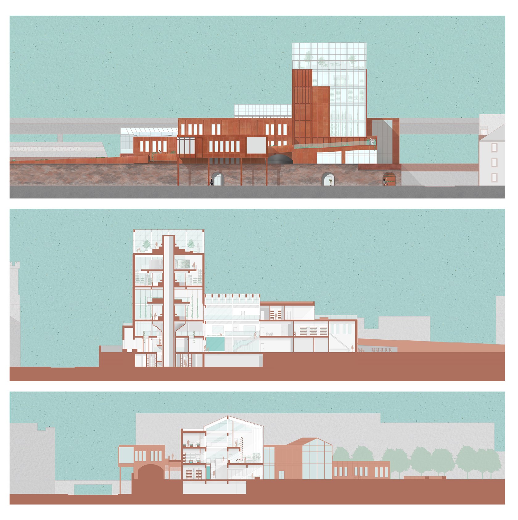
Elevation and Sections
Structural appraisal
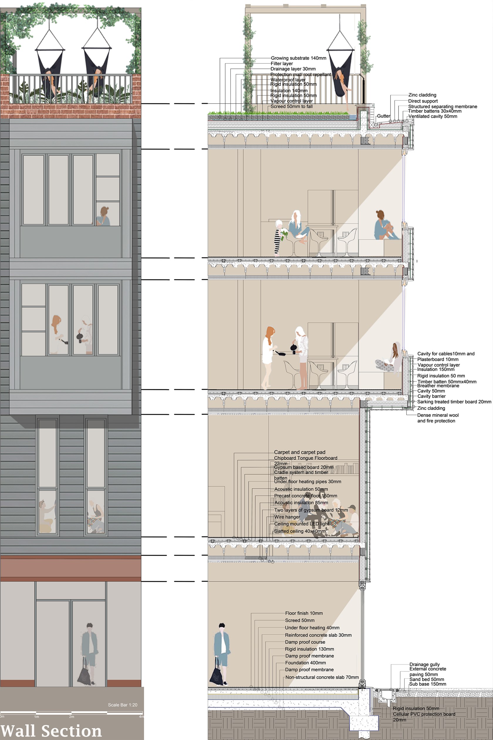
1:20 Wall Section
Vertical section, Roof at 1:5
Technical detail
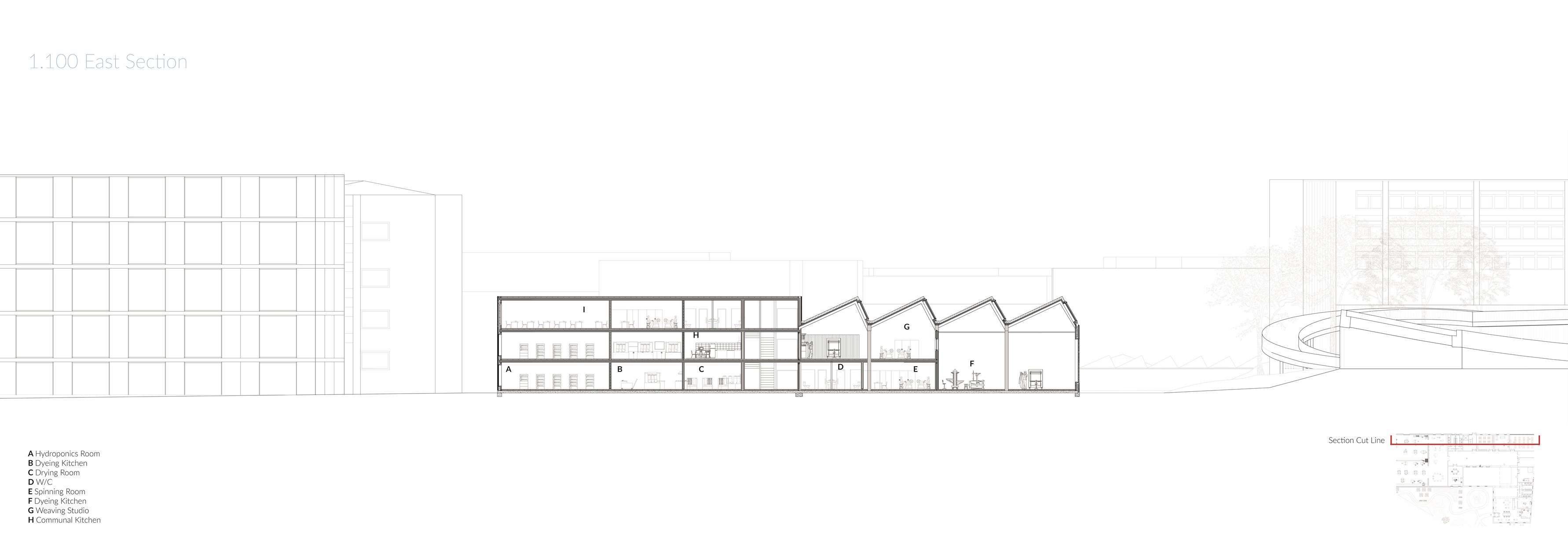
1:100 East Long Section
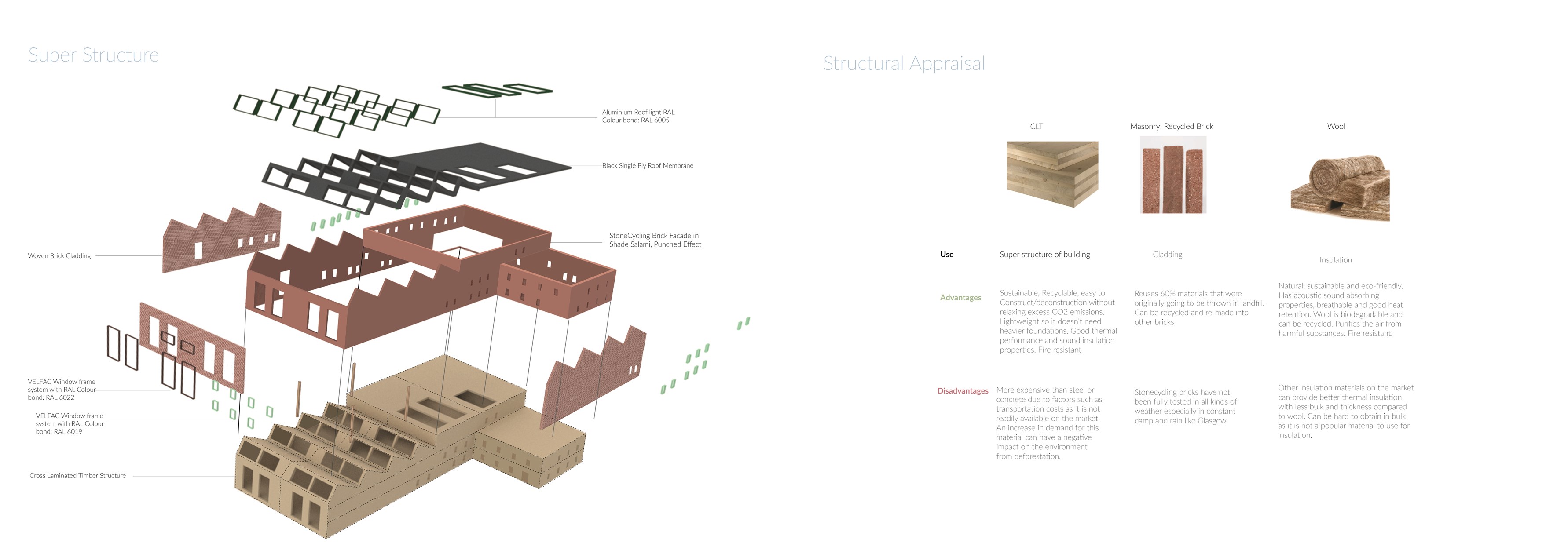
Super Structure and Sustainable Material Evaluations
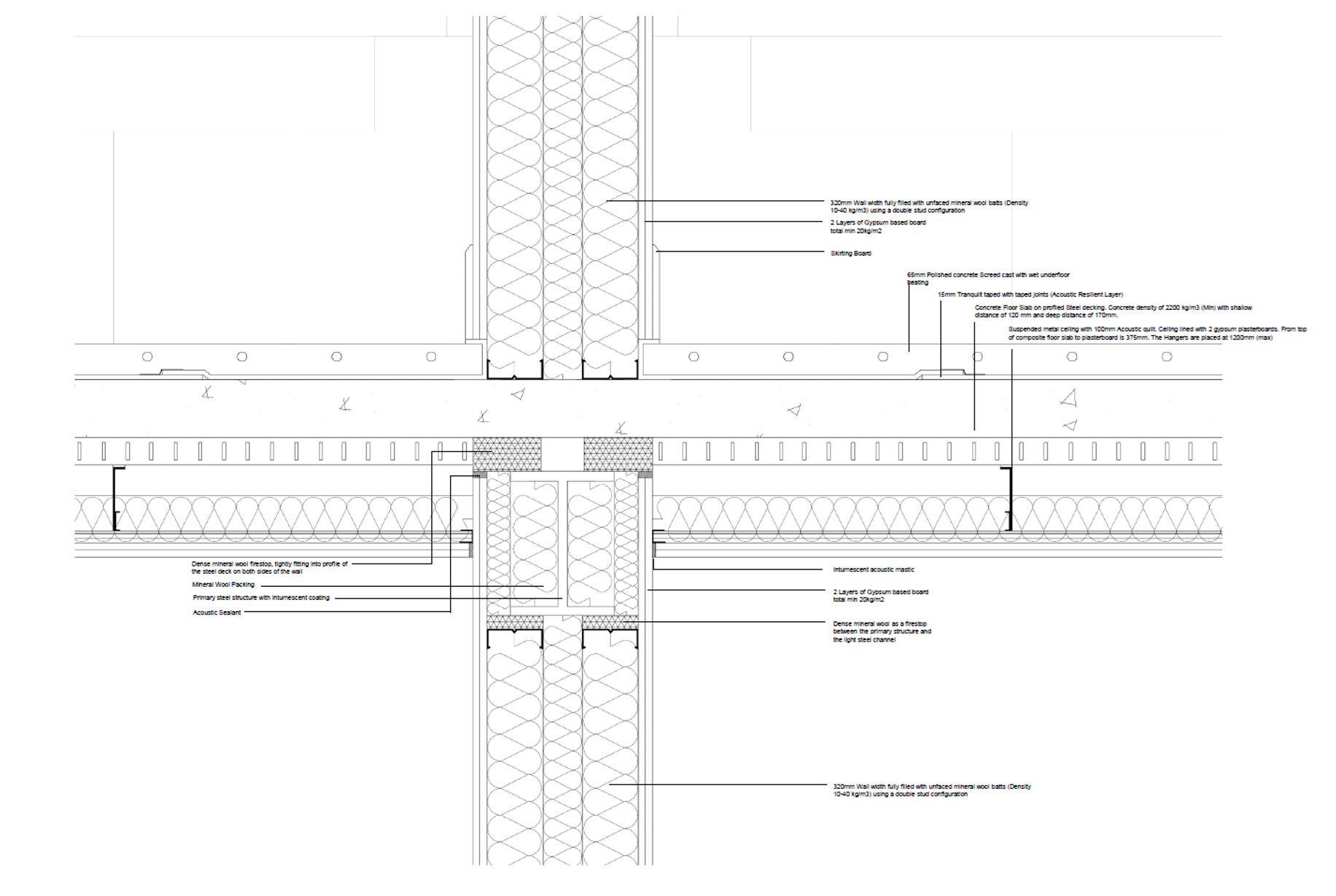
1:5 Technical Detail: Separating Wall & Separating Floor

Technical section and elevation

Stair Design
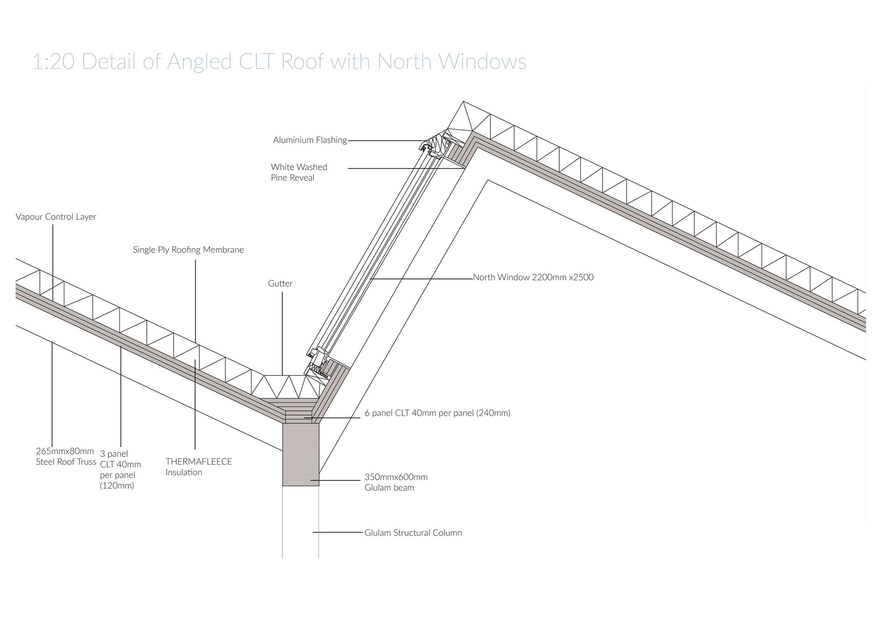
1:20 Detail of CLT Roof and North Skylight
Building Section
Technical Section and Façade Study
Structural Detail
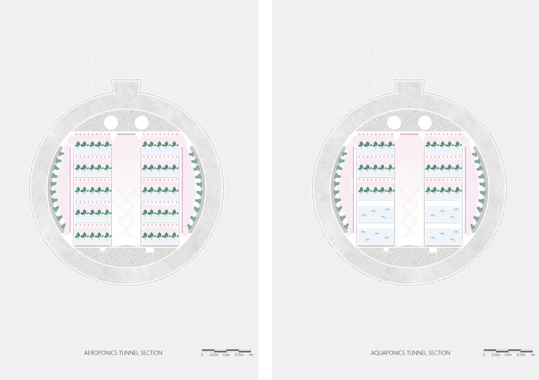
Typical section through production tunnels

1:5 Technical Detail: Separating Floor to External Wall

Long section of The Floating Facility and Plans